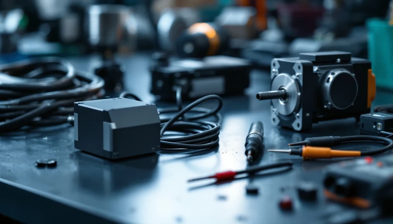
An axis faults with an overcurrent-class alarm — FANUC alarm 8/12-series, Mitsubishi AL.32, Yaskawa A.10 — and you're staring at the two most expensive suspects on the machine: the servo amplifier and the servo motor. Guess wrong and you either replace a healthy amplifier, or worse, install a good amplifier onto a shorted motor and watch it die in seconds.
Here's the field-level isolation that costs nothing but a megohmmeter and twenty minutes. As of August 2026 it is still the highest-value twenty minutes available on a down axis, because it decides whether you are in repair territory, rewind territory, or mechanical territory before a dollar moves.
First: what the alarm is actually saying
An overcurrent/IPM alarm means the amplifier's power stage saw current beyond its limit and shut down to protect itself (or failed trying). Three things cause that:
- The amplifier's own power stage failed — a shorted IGBT or intelligent power module (IPM). The most common servo amplifier failure, period. Often announced by the alarm appearing the instant the drive enables, or the machine breaker tripping at power-on.
- The motor or its cable is shorted — winding-to-winding or winding-to-ground. The amplifier is (so far) healthy and doing its job by faulting.
- A mechanical jam demanded more current than the axis limit — less common, and usually obvious from what the machine was doing.
The reason this split matters so much is the failure coupling: a shorted motor destroys amplifiers. Feed a fresh power stage into a winding short and the new IGBTs see the same dead short the old ones died into. That is why the isolation below runs motor-side checks before any amplifier gets connected to anything.
Safety first, and not as a formality
Two hazards in this procedure deserve respect rather than ritual.
The DC bus. Servo amplifiers rectify incoming AC onto a capacitor bank that can hold hundreds of volts for minutes after power-off. Verify the bus is discharged with a meter before touching power terminals — the charge lamp going out is an indication, not a verification. The OSHA lockout/tagout standard applies to exactly this class of stored-energy work, and the arc-flash and shock-protection practices in NFPA 70E from the National Fire Protection Association are written for cabinets like the one you are about to open. If your plant has an electrical safety program, this task is inside it.
The megger itself. A 500V insulation test applied to the wrong terminals — encoder lines, or motor leads still landed on the amplifier — destroys electronics that were perfectly healthy. Disconnect first, test second, and never megger toward the drive.
The 20-minute field isolation
Step 1 — Read the timing. Alarm at enable/power-up with the axis doing nothing → lean amplifier. Alarm only under load, during rapids, or at a particular spot in travel → lean motor/cable/mechanics.
Step 2 — Disconnect the motor leads at the amplifier (machine locked out, drive powered down, DC bus verified discharged — these buses hold lethal charge after power-off).
Step 3 — Megger the motor + cable. With the leads off the amp, test insulation resistance from each motor phase to ground at 500V. Healthy: hundreds of megohms. A reading in the low megohms or kilohms = shorted motor or cable — do not connect a good amplifier to it. Also check phase-to-phase resistance with a plain multimeter: the three readings should match closely; a significantly low pair suggests a winding short.
Step 4 — Power the amplifier with the motor disconnected (where the platform allows). Many amplifiers will sit enabled with no motor and no alarm if their power stage is healthy; an amp that faults instantly with nothing connected has convicted itself.
Step 5 — Check the amplifier's power stage passively. With everything isolated, a multimeter in diode mode across the amplifier's output terminals to the DC bus terminals will reveal a dead-shorted IGBT leg on most units — a reading near zero ohms where its neighbors read a normal diode drop.
| Evidence | Points at | Next move |
|---|---|---|
| Alarm the instant the drive enables, axis commanded nothing | Amplifier power stage | Diode-mode check, then bench repair |
| Breaker or fuse blows at power-on | Amplifier (shorted IGBT leg) | Do not keep resetting it — each attempt stresses what is left |
| Megger shows low megohms or kilohms to ground | Motor or cable | Rewind/replace path; do NOT connect a good amp |
| Phase-to-phase resistance unbalanced | Motor winding short | Same — motor side, amp is likely a victim or fine |
| Alarm only under load or at one spot in travel | Mechanics or motor under stress | Check the axis by hand; megger warm if possible |
| Amp runs enabled with motor disconnected, faults when connected | Motor/cable side | Split the cable from the motor and test each |
| Diode-mode reading near zero on one output leg | Amplifier convicted | Repair, not replacement — see costs below |
One refinement worth knowing: insulation faults are temperature-dependent. A motor that meggers acceptably cold can fail hot, which is why an under-load-only alarm justifies re-testing after the axis has run — and why the alarm history matters more than any single reading.
Why power stages fail on schedule
IGBT modules fail from thermal cycling — every acceleration heats the die, every dwell cools it, and the solder and bond wires inside the module accumulate that stress for years. The power-electronics reliability literature published through IEEE identifies thermal cycling as the dominant wear-out mechanism in exactly this component class, and EPRI reliability work on industrial power conversion points the same direction. The supporting cast ages too: the DC bus electrolytics dry out, ripple grows, and the power stage runs harder than its design assumed.
That is why a proper amplifier repair is never just swapping the failed module. It is a new IPM or IGBT set (new components, not pulls), gate-drive verification — because a failing gate driver kills the replacement module — a bus recap, and a powered load test. Skip the gate-drive check and the repair lasts a week; do it properly and the repaired amplifier is, in the ways that matter, younger than the one that failed. This is the standard scope on our servo drive repair bench.
What each verdict costs
- Shorted motor/cable: motor rewind or replacement territory — and be glad you didn't feed it a fresh amplifier.
- Failed amplifier: a repair, not a replacement. IGBT/IPM replacement with new components, gate-drive verification, DC-bus recap, and powered testing typically runs $450–$950 on Mitsubishi MR-J2S-class amps and $650–$1,500 on FANUC alpha-series — against replacement exchange units at $2,500+ and new units that may not exist anymore.
For the platform-specific version of that decision, the MR-J2S repair-exchange-migrate guide walks the Mitsubishi paths, the Yaskawa A.10 guide covers the Sigma-series version of this exact alarm, and the FANUC A06B part-number reference decodes which alpha-series amplifier you actually have before you price anything.
The economics of guessing wrong deserve one more sentence. With Bureau of Labor Statistics data putting skilled maintenance labor well north of fifty dollars an hour fully loaded, and downtime on a production axis worth multiples of everything in this article per hour, the twenty-minute isolation is not a diagnostic nicety — it is the cheapest insurance in the building. The Department of Energy has spent years making the same point about condition-based maintenance generally: measuring before spending is where the money is.
If you'd rather not open anything
Fair. Ship us the amplifier with the exact alarm number and what the machine was doing — the evaluation is free. We test the amplifier independently on the bench: if it's healthy, you pay nothing, and you've just cleared the expensive suspect and can chase the motor side with confidence. If it's failed, you get a firm quote before any work happens, and the repair carries the 24-month warranty like everything else on the bench. Start a repair online in two minutes when you are ready to ship.
Either way: never "test" a spare amplifier on an un-meggered motor. That experiment has a 100% documented cost and a 0% information yield.
Frequently asked questions
How do I know if the servo alarm is the amplifier or the motor?
Read the timing first: an alarm the instant the drive enables points at the amplifier's power stage, while an alarm only under load or at one spot in travel points at the motor, cable or mechanics. Then confirm with two measurements — a 500V insulation test on the disconnected motor and cable (healthy readings are hundreds of megohms), and a diode-mode check across the amplifier's output legs (a near-zero reading convicts a shorted IGBT). Twenty minutes settles it.
Can a bad servo motor destroy a new amplifier?
Yes, and quickly — this is the most expensive mistake in the whole category. A winding shorted to ground or phase-to-phase presents a dead short to the amplifier's power stage, and a fresh amplifier connected to it typically fails within seconds of enabling. Never connect a known-good amplifier to a motor that has not passed an insulation test.
What does servo amplifier repair cost?
As of August 2026, a proper power-stage repair — new IGBT or IPM modules, gate-drive verification, DC-bus recap and powered testing — typically runs $450 to $950 on Mitsubishi MR-J2S-class amplifiers and $650 to $1,500 on FANUC alpha-series, with a free evaluation first and a 24-month warranty after. Replacement exchange units for the same families commonly run $2,500 and up on the secondary market, where they exist at all.
Why does the machine breaker trip the moment I power on?
That is the classic signature of a dead-shorted IGBT leg in the amplifier: the shorted device puts a direct path across the DC bus, and the inrush trips the breaker or blows the fuse immediately. Stop resetting it — every attempt hammers the components that survived. Confirm with the diode-mode check and send the amplifier for repair.
Is it safe to megger the motor myself?
It is routine electrical work, with two rules. First, the motor leads must be fully disconnected from the amplifier before any insulation test — 500V applied toward drive electronics destroys them. Second, treat the amplifier's DC bus as charged until you have verified otherwise with a meter, and do the work under your plant's lockout/tagout procedure. If either rule is unfamiliar, this is a job for your electrician, not a shortcut.
The motor meggers fine but the alarm still comes back. Now what?
Then the remaining suspects are the amplifier under real load, the encoder path, and the mechanics. Re-test the motor hot if the alarm correlates with run time, check the axis moves freely by hand where the machine allows it, and have the amplifier bench-tested independently — a free evaluation that clears or convicts it without guesswork. An amplifier that passes a full powered load test on the bench turns the investigation firmly back toward the machine.
Have this exact problem?
Start a repair or get a free technician review — we'll tell you honestly whether it's worth fixing.